Understanding steam control valves
Published: 24 February, 2014
Kelly Paffel from Swagelok, reviews some of the most common items to understand best practices for steam control valve installation.
The steam control valve is one of the most basic and indispensable components of the steam system, and plays a very important role in the quality of the products that the plant is producing. All steam control valves should have an operational life of at least six years due to available technology and current material standards, and proper installation will greatly prolong the life of the valve. Understanding proper installa¬tion and application of the steam control valve is essential to experiencing maximum value and life cycle from the valve.
By definition, a valve is a device that controls the flow of a fluid or vapour. Steam control valves not only control the pressure, but also the temperature in process applications. The steam control valve can be used simply as an on and off device, or any combination of controlling to include regulation, modulation, mixing, or even isolation. Valves can range in size from a 1/2 inch to as large as 28 inches in diameter.
The control valve is one of the oldest products used in the steam system. Today, there are a variety of valves used in a myriad of different and demanding steam applications:
1. Leak Rates for Valves
All valves including steam control valves are designed to meet a designated internal permis¬sible leak rate standard (FCI/ANSI). There are six permissible leak rates or Classes num¬bered I through VI. The higher the leak rate number, the lower permissible internal leak rate. Therefore, a Class I valve will have the highest internal leak rate and usually the lowest cost; while a Class VI valve will have the lowest permissible internal leak rate.
Identifying the permissible internal leak rate for a valve has to be one of the top priorities when choosing the correct steam control valve. A valve with a high leak rate, will cause excessive wear or “wire drawing.” The valves with a high leak rate will pass more steam internally and can result in premature valve failure. Steam valves should be specified to have a leak rate of no less than Class IV. A Class IV steam control valve will maintain a long operational life.
2. Steam Line Drip Pocket
All steam control valves must have a condensate removal drip pocket piped upstream of the control valve. The drip pocket removes condensate from the steam line, preventing condensate from passing through the valve. This is essential because condensate permitted to pass through the valve will cause erosion and shorten the life of the valve. More impor¬tantly, when the steam control valve shuts off during low or non-production periods, the condensate drip pocket will remove accumulating condensate from the inlet of the steam control valve.
3. Strainer
All steam control valves must have a strainer ahead of the valve. Steam lines frequently contain residual solid materials from the corrosion and other impurities. The strainer will filter the steam stream and prevent this material from lodging in the valve internals which would cause premature failure. The strainer should be rated for 0.020 perforated stainless steel mesh and never be mounted with the strainer segment in a down position. Rather, install the strainer segment in a horizontal position (see detail). This will prevent condensate from accumulating in the pocket and then passing through the control valve increasing the likelihood of internal erosion and premature failure. The Strainer will have a calculated drop across the unit. The equation to determine the pressure drop:
Ps = 91
4. Pneumatic Actuation
The preferred method of actuating the steam control valve is a pneumatic actuator. These actuators are reliable and should provide the plant with over 20 years of opera¬tion. Heat from the steam in valve body is dissipated in the yoke assembly away from the actuator ensuring long life of the pneumatic diaphragms.
5. Actuator Positioning
Always install the actuator in the upright position on a vertical line horizontal. This will prevent condensate from accumulating in the packing gland area and causing packing damage.
6. Specify 85 DBA or Lower
Control valves that have high DBA levels will also have high outlet velocities. A valve with low DBA levels or lower velocities will have a much longer operational life. There are many ways to lower the DBA level in a steam valve application; increasing the size of the valve outlet pipe or special trim may be required to lower the DBA.
7. Enlarge the Discharge Piping
Always expand the discharge steam line piping at least one pipe diameter. It is not uncom¬mon to expand the discharge piping at least two or three pipe diameters. The expansion of the pipe reduces the valve outlet velocities thus prolonging the valve life.
The valve manufacturer will provide the appropriate pipe size after the control valve.
Always match the pipe size to the heat transfer inlet connection. For example, assume a 3 inch control and with a heat transfer inlet connection of 8 inches. For this scenario, the pipe size at the outlet of the steam control valve should be increased to 8 inches.
Muffling orifice plates can be used to reduce a high pressure drop across the steam valve and reduce velocities.
8. At Least Ten (10) Pipe Diameters After the Control Valve
The distance after the steam control valve should be at least 10 pipe diameters before the inlet connection of any heat transfer. Pressure reduction applications should have at least 20 horizontal pipe diameters before a change of flow direction.
9. Valve Positioning
The control valve should always be installed on a horizontal steam line, never vertically. A control valve in a vertical installation has no ability to eliminate the build-up of condensate prior to the inlet of the control valve. Condensate passing through the steam control valves always has negative effect on the valve life.
10. Valve Turndown Requirements
Understanding the control valve turn down capabilities is very important. When sizing a control valve, always size on maximum flow. The minimum flow will be a frequent con¬trol point as compared to operation at the high flow rate. Therefore, the steam control valve must be able to operate successfully at the low flow rates. It is more important to properly select the valve at low flow operat¬ing conditions that at its assumed high flow operating conditions.
Often, there are times when more than one control valve is needed to meet the perfor¬mance of the process application.
a. 20 to 1 Regulator
b. 30 to 1 Globe Valve
c. 40 to 1 Cage Control Valve
11. Bypass Valve or Warm Up Valves
Bypass valves and warm up valves should be used in control valve installation. In an application of pressure reduction, the warm up valve is used to warm the steam line, within recommended time frames, before the control valve is placed into operation.
A steam control valve should not be used for warm up of a steam distribution line. Additionally, the by-pass valve is used in a process application to allow plant personnel to operate the process without the control valve, if valve failure occurs.
12. Pressure Gauges (before and after)
It is always a good practice to install pres¬sure gauges before and after the steam control valve as diagnosis tool. Ensure to include a siphon pipe and isolation valve for maintenance purposes. In systems with high vibrations, use liquid filled gauges to extend the life of the pressure gauge.
For further information please visit: www.swagelok.com
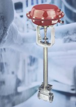 When precise, reliable flow control is required in challenging ultra-low temperature applications, such as cryogenic or other similar situations, Badger Meter control valves are said to be an ideal choice. Available from liquids handling specialist PUMP ENGINEERING, the extensive Badger range includes models such as the Series 9000, an ANSI Class 300 globe style valve with bolted bonnet and post-guided inner valve.