Bearing condition monitoring using ultrasound
Published: 20 March, 2023
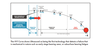
Airborne & structure-borne ultrasound has become a major player in bearing condition monitoring. Once considered just a leak detector, more maintenance & reliability professionals are beginning to realise all of the benefits associated with using ultrasound for condition monitoring applications. The P-F Curve with which we have all become familiar with reflects that trend.
It has been said that at least 60% of premature bearing failures can be attributed to lubrication, whether it’s over lubricated, under lubricated, using the wrong grease for the wrong application, or contaminated lubricant. Ultrasound instruments can be used to prevent over and under lubricated bearings. Since the source of ultrasonic noise is friction, when a bearing is in need of grease, there is an increase in friction; therefore, an increase in noise or decibel level. When listening to the bearing that is in need of lubrication and watching the decibel level on the display of an ultrasonic instrument, as grease is applied the inspector would notice a gradual drop in the decibel level, and eventually back down to a more normal level. If the bearing is already over lubricated, as soon as grease is applied, the inspector would notice a gradual increase in the decibel level, letting them know that the
How do I get started?
There are two common questions that many first-time users of ultrasound have. The first is, “how do I set baselines?” The second is, “how do I know if what I’m listening to is good or bad?”
The comparison method
One way to get a quick idea as to what is good and what is bad is by using the comparison approach. With this method, the inspector simply compares the decibel level readings at identical points on identical machines. Using this method, the inspector also begins to “train” their ear as to what rotating equipment sounds like, and it will become obvious that a bearing with a particular fault such as an inner race, or outer race defect, will sound much different than a bearing that is in a “good” condition. The baseline can then be set based off an average of decibel levels at the compared points. The software may even default to the first reading taken and downloaded. The baseline can then be changed as more readings are collected.
The historical method
The historical method is the preferred method for establishing baselines and alarm levels in bearing condition monitoring routes. Using this method, the inspector first establishes a route or database in the ultrasound software. The database is then loaded into the ultrasonic instrument. Data is then collected at the various points along the route. When the initial round of data is collected, it may be necessary to collect data more frequently than needed in order to build the history, and get an idea if the decibel readings are remaining similar in the historical readings.
For example, when collecting the initial data for setting the baseline, the readings may need to be taken once per week for 4-5 weeks. Once the baseline is set, the readings can be taken only once per month, or every other month depending on asset criticality and equipment runtime.
Ultrasound imaging
Through advancements in ultrasound instruments and software, the user can obtain an “image” of the sound that is being heard to analyse, diagnose, and confirm mechanical fault conditions in rotating equipment.

Examples of ultrasound imaging Let’s take an example from two motor and pump combination: 60hp motors powering water pumps.
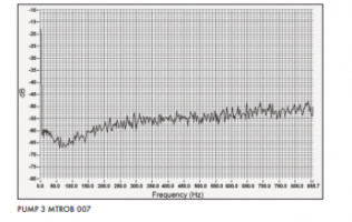
While collecting data, both decibel readings and sound files were recorded. The below screen shots from the spectral analysis software show a comparison between the points “PUMP 3 MTROB 007” and the “PUMP 4 MTROB 010.”
Notice the difference between the two points. Both motors are operating under the same conditions, but the Pump 4 MTR OB point has a much different spectrum. If you were listening through the headset of the ultrasound instrument, it would also have a much different sound.
The spectrum analysis software used has a built-in bearing fault frequency calculator. By entering in the speed (rpm) and the number of balls (bearings), an outer race, inner race, ball pass, and cage frequency are calculated. For this particular motor, the speed was 1750rpm and the type and number of bearings was confirmed and the number of bearings was 10. The fault frequency calculated by the spectrum analysis software that was of interest was an inner race fault at 175Hz. This is the same fault harmonic detected on the ultrasound instrument. Another interesting point was the fact that the vibration analysis data was collected two days later, and did confirm an inner race fault on the Pump 4 motor outboard point.
Conclusion
Implementing ultrasound for condition monitoring applications is easier than you think. With a short learning curve, ease of collecting data, and remote monitoring solutions, ultrasound can become another valuable tool to use for your condition monitoring efforts.
Lubrication PM’s can also become more effective because ultrasound trends will show which bearings need to be lubricated. Therefore, instead of greasing everything on a time-based lube route, only the points that are currently in the lubrication alarm from ultrasound trends are greased until the decibel level drops back down to the baseline dB.
If you’re only using ultrasound as a leak detector, I would encourage you to take a more in depth look into condition monitoring with ultrasound


