A force to be reckoned with
Published: 07 May, 2014
The importance of force friction ratio in determining valve reliability and performance in the energy sector. Richard Harvey, key account manager, Norgren, reports.
Ever more stringent international safety requirements on valves, such as IEC 61508 and 61511 standards, are creating a growing requirement to design products offering optimum performance in the most demanding conditions.
Historically, many solenoid valves not originally designed for these applications were used, potentially compromising overall system performance and giving them an undeserved reputation for unreliability. Meanwhile, as well as Cv, temperature rating and certification, designers have often relied on mean time between failure (MTBF) to judge valve reliability.
However, as MTBF frequently relates to how many operations a valve can withstand, more relevant in low demand mode applications is a measure of how likely the valve is to close on demand. Probability of Failure on Demand determines the likelihood that a valve will operate if required - but tells the operator nothing of a valve’s intrinsic design principles, leading to the concept of Force Friction Ratio (FFR).
What is Force Friction Ratio?
FFR measures the relationship between the force presented by the spring return mechanism and frictional resistance within the valve. In principle, maximising FFR sounds easy, using a large, powerful spring. However, as spring force increases, so does the required magnetic flux from the solenoid to open the valve and hold it open, increasing electrical power required to operate the valve.
Causes of friction
Friction is caused by o-ring seals interacting with the valve body. There are two types of seal interfaces – dynamic, or spool type seals, and static, also known as ‘poppet’-type seals. In a static seal the seal only interacts with the body at the end of the valve travel, where it contacts a flat surface in the body. This seal type has minimal effect on friction.
In dynamic seals, the seal is in contact with the valve body throughout valve movement. They can impact significantly on friction as the seal is laterally distorted against the valve body surface. The more dynamic seals, the higher the friction. An additional drawback is the effect of thermal expansion on both friction and seal quality.
Lubricant condition, time between operation, presence of debris and contamination, and temperature cycling can also all cause frictional forces experienced by the dynamic seals to increase over time, reducing FFR.
Mechanical operation of a solenoid valve
All solenoid valves in process industry are poppet or spool type valves.
In this 2/2 poppet valve there is only one static seal performing the isolation process. Two dynamic seals isolate process media from the valve’s “dry armature” assembly. The spring must overcome the frictional resistance of two dynamic seals. A 3/2 design would require a further single static seal and no dynamic seals.
A typical 3/2 spool type valve has four dynamic seals, doubling the poppet-type assembly’s frictional resistance.
Coil Housing Design
To maximise magnetic force, magnetic field lines must be uniform and concentrated.
These lines follow the path of least resistance and are easily concentrated in magnetic metals but any gaps in the construction around the coil will cause a “leakage” in magnetic flux and thus power loss. However, minimising magnetic flux leakage is not so simple in the area surrounding the coil as this is the solenoid valve’s body and issues such as ease of assembly and servicing must be considered. Magnetic flux leakage can be minimised by a solid, uniform housing surrounding the coil.
Core materials
The valve core is a section of magnetic material upon which the magnetic field is concentrated. When the coil is energised, the magnetic field acts upon the core, generating a magnetic force which acts on the armature, causing it to operate the valve. Core materials’ magnetic properties impact significantly on the core’s ability to generate a strong magnetic field, therefore affecting valve operation.
Magnetic materials contain localised magnetic dipoles in “domains”. In untreated materials, these are arranged randomly giving zero net magnetism. However, when a magnetic field is applied, they align their dipoles to create a magnetised material. When the field is removed, a percentage of dipoles return to an unmagnetised state.
The key property of any magnetic material used for the valve core is the dipoles’ ability to align and then return to normal. This “magnetic flux density” is critical in core material selection
The x-axis is the magnetising force applied and the y-axis the material’s magnetic flux density. In solenoid valves, the magnetising force is directly proportional to current applied and magnetic flux density directly proportional to the force applied to the valve armature.
With no applied magnetising force, there is no magnetic flux. As applied magnetising force increases, so does the magnetic flux density (the dashed line, indicating a non-linear relationship)
Once the material has reached magnetic saturation and when the magnetising force reduces, the magnetic flux density follows the curve to a point . Here, there is no applied magnetising force, but there is still residual magnetic flux density. This “retentivity” is critical for core material selection as this residual magnetic flux will work against the solenoid valve spring, reducing effective FFR.
When the coil is next energised, the curve will move from the origin to a point. As the coil current is increased there is initially no increase in magnetic flux or force applied to the valve armature. This is called “coercivity” and as with retentivity, the higher the coercivity, the less suitable the material. As the magnetising force is increased it will continue from point to point - the same path it will take for all subsequent energising operations.
Hysteresis curves are for two different materials. Materials with a narrow curve are called “soft magnetic” and those with a wide curve “hard magnetic”. The narrower the curve, the lower the retentivity and coercivity, therefore the more suitable the core material for delivering high FFR. However one important feature limits material selection – use of wet or dry armatures.
With a wet armature, the core material is exposed to the process media so must be corrosion-resistant. Most “soft magnetic” materials have lower corrosion resistance. Corrosion-resistant magnetic materials typically have high carbon content but are generally “hard magnetic”. To use a “soft magnetic” core material, a dry armature design must be selected.
Heat dissipation
The final key issue is excess heat dissipation. When energised, electrical coils generate heat which must be dissipated to maximise coil efficiency. The best method is a good thermal path to the atmosphere, allowing air cooling, meaning all materials used between the coil and atmosphere should offer good thermal conductivity.
Thermal conductivity, k, is measured in Wm-1K-1. The thermal conductivity of stainless steel has thermal conductivity is approximately 700 times better than air - meaning any air gaps in the construction dramatically reduce heat dissipation capabilities, so reducing magnetic force generated in the valve. Measured in oC, this is often quoted as the valve’s ΔT. The lower the ΔT, the better the performance, and the higher the FFR.
What makes an ideal solenoid valve design for high FFR?
Valves designed to the following rules will be optimised for a high FFR.
a. Reduce friction by using a poppet-type design to minimise dynamic seals
b. Regular, continuous coil housings reduce magnetic flux leakage
c. A dry armature allows use of a soft magnetic core material, improving magnetic flux density
d. Minimising air gaps in the thermal path between the coil and external surfaces improves heat dissipation, optimising improving solenoid valve efficiency
e. Use the maximum spring power permissible by optimising parameters a to d
For further information visit www.norgren.com/uk/energy
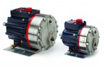 WANNER says its Hydra-Cell seal-less pumps, have solved a pump seal wear problem for a major producer of acoustic panels. When pumping abrasive coatings, pumps with dynamic seals can eventually wear and leak, performance accuracy deteriorates and maintenance downtime for seal replacement can prove expensive as the Corporation found to its cost.